
Well Diagram
This illustration is intended to represent some of the components that can be included in a water well system and is not intended as an installation guide.
Check local or state codes for actual requirements and restrictions.
Sample Water Well System
Hover over a numbered part to see its name. Descriptions are listed below.
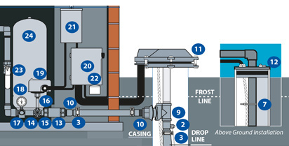

- (1) Check Valve – Located at the top of the pump to hold water in the tank and prevent backflow through the pump.
- (2) Rope Insert Adapter – A male or female pipe adapter with a loop for attaching a pump safety rope or cable. Constructed of stainless steel or brass.
- (3) Clamps – Provide connections between Pipe and Insert Fittings or Torque Arrestor.
- (4) Heat Shrink Splice Kit – Enables waterproof electric cable splices in submersible pump installations.
- (5) Torque Arrestor – Installed directly above Submersible Pump to protect pump and well components from starting torque damage.
- (6) Safety Rope – A safety line from the top of the well to the pump.
- (7) Cable Tie or Tape – Fastens cable to drop pipe.
- (8) Cable Guard – Protects submersible cable wires from abrading against sides of well and holds drop pipe and pump in the center of the well.
- (9) Pitless Adapter – Provides a watertight sanitary removable connection between pump and house. Installed in casing below the frost line to prevent freezing.
- (10) Male or Female Insert Adapter – A pipe fitting that is threaded on one end, with serrations for attaching polyethylene pipe on the other end. Constructed of stainless steel, galvanized steel, brass or plastic.
- (11) Watertight Well Cap – Provides a watertight seal when its inner gasket compresses to outside diameter of casing. Top of cap removes easily to access well for service.
- (12) Well Seal – Provides a positive seal inside casing in above-ground installations.
- (13) Check Valve – Installed near the tank inlet to hold water in the tank during pump installation when the pump is idle.
- (14) Tank Tee – Connects water line from pump to pressure tank and service line from tank to house. Taps are provided to accept Pressure Switch, Pressure Gauge, Drain Valve, Relief Valve, Snifter Valve, etc.
- (15) Drain Valve – Promotes easy draining of the system.
- (16) Nipple – Male threads allow attachment of Pressure Switch to Tank Tee.
- (17) Relief Valve – Protects against pressure build-up. Should be used on any system where the pump could develop pressure that exceeds the maximum system rating.
- (18) Pressure Gauge – Measures water pressure in Pressure Tank.
- (19) Pressure Switch – Signals the pump to start when the water system drops to a pre-set low pressure, and to stop when the high-pressure mark is reached.
- (20) Power Disconnect – For electric control and distribution to the pump.
- (21) Control Box – Adjustable, solid state control monitors system load conditions to protect pump motor from dry well, flow loss, rapid cycling, slow recovery, air lock and locked rotor problems.
- (22) Lightning Arrestor – Protects pump motor and controls from voltage surges caused by lightning, switching loads and powerline interference.
- (23) Ball Valve – Acts as a shutoff valve on the supply line from tank to house.
- (24) Pressure Tank – A storage vessel containing air and water that provides storage of water under pressure for delivery between pump cycles; allows for reserve capacity for periods of peak demand; protects and extends the life of the pump by reducing the number of on/off cycles; and helps reduce overall system maintenance.
- (25) Pump – A machine capable of lifting, raising or moving water from a well or tank to a higher elevation or a distant location. A pump can create pressure and/or increase the velocity of water.